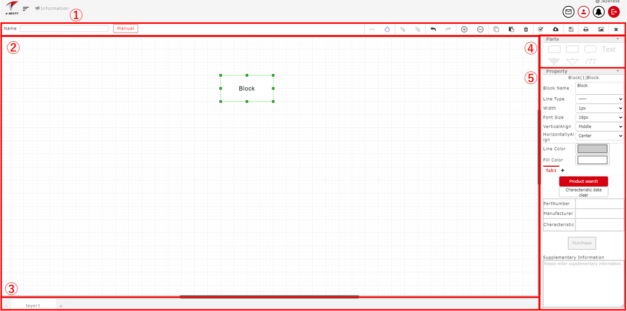
Screen structure

① Menu bar
You can perform various operations using the functional buttons at the top menu.
- Name ・・・ Set a name of a block diagram.
- Manual ・・・ Open the block diagram operation manual in a separate tab.
- Switch to connect ・・・ Switches to a mode where you can create a connect from a block.
- Switch to move ・・・ Switches to a mode where the block can be moved.
- To Front ・・・ Bring the selected block to the front.
- To Back ・・・ Move the selected block to the back.
- Undo(←) ・・・ Discard the last operation and return to the previous one.
- Redo(→) ・・・ Execute the previously ‘Undo’ operation.
- (+) ・・・ Enlarge the drawing area of the block diagram.
- (-) ・・・ Shrink the drawing area of the block diagram.
- Copy ・・・ Copy the selected block diagram.
- Delete ・・・ Delete the block selected in the drawing area.
- Self check ・・・ Check if the block diagram is successfully built.
- Import block diagram ・・・ Import another block diagram into the current block diagram.
- Save ・・・ Save the block diagram.
- Save as ・・・ Save the block diagram being edited with a different name.
- Print ・・・ Display the Print page.
- Output image ・・・ Download the block diagram image (SVG/PNG).
② Drawing area
- Drawing area ・・・ Drag and drop parts to draw a block diagram. You can scroll the drawing area up and down using the scroll bar on the right.
- Right click ・・・ Right click and select appropriate function to manipulate an item.
- Drawing area:
- Undo ・・・ Discard the last operation and return to the previous one.
- Redo ・・・ Execute the previously ‘Undo’ operation.
- Block:
- Delete ・・・ Delete a block.
- Copy ・・・ Copy a block.
- To Front ・・・ Bring the selected block to the front.
- To Back ・・・ Move the selected block to the back.
- Switch To Link ・・・ Switch from a block to a module link.
- Switch To Block ・・・ Switch from a module link to a block.
- Hide Image ・・・ Hide the image associated with the selected category.
- Show Image ・・・ Show the image associated with the selected category.
- Drawing area:
③ Layer
The details of the module link associated with the block diagram are displayed in each layer tab.
- Menu ・・・ Click the icon on the left of the layer list to display the menu and execute the appropriate function.
- Select layer ・・・ Display the selected layer in the drawing area.
- New Layer ・・・ Create a new layer.
- Delete ・・・ Delete the selected layer.
- Rename ・・・ Rename the selected layer.
- Copy ・・・ Copy the selected layer.
- Right click ・・・ Right-click on a layer tab to execute the appropriate function.
- New Layer ・・・ Create a new layer.
- Delete ・・・ Delete the selected layer.
- Rename ・・・ Rename the selected layer.
- Copy ・・・ Copy the selected layer.
- New Layer ・・・ Click the "+" icon on the right of the layer list to create a new layer.
- Rename layer ・・・ Double click the layer to change the layer name.
- Change layer order ・・・ Drag the layer to change the order of the layers.
④ Part
The parts used in a block diagram. Drag & drop the parts into the drawing area for use.
- Block ・・・ The main part used in a block diagram. You can connect to a block with others and configure product properties. When you switch from a block to a module link, the stored product property information is reset.
- Textbox ・・・ The part used to insert text to the drawing area.
- Frame ・・・ The part used to divide blocks into groups. You can connect frames to each other.
- Round Rectangle ・・・ This is a part for grouping blocks. Connect connection is possible.
- Earth Ground ・・・ This part indicates grounding. Connect connection is possible.
- Signal Ground ・・・ This part represents the signal ground. Connect connection is possible.
- Frame Ground ・・・ The part that represents the frame ground. Connect connection is possible.
⑤ Properties
- Properties ・・・ Set the properties of each part.